
BIM and GIS: complete study of a lineal road project

Study of layout alternatives for a linear road project in the planning phase using BIM methodology based on Geographic Information Systems, for the first practical part of Block I of the International Master’s Degree in BIM Manager in Civil Engineering, Infrastructure, and GIS by the ConectaBIM group formed by the ITASE 04 team of 2020.
In recent years, significant technological changes have been taking place aimed at improving the planning, control, and development of building and infrastructure projects. The BIM methodology is spearheading these changes ; its implementation is a reality in our country and is increasingly a priority among major companies and public administrations. The use of BIM allows for the optimization of the entire life cycle of a project based on a digital model, where all the information generated by the stakeholders involved is coordinated and centralized. In this article, we will focus on the planning phase, where decisions are made that determine the degree of optimization of the project and that will affect all phases of the project. To achieve this, the creation of a digital model that allows a rapid understanding of the entire project , the selection of the most appropriate information it should contain, and facilitating workflows among the stakeholders involved will be factors that will determine a better decision-making process.
Computer equipment and software used
EquipmentTo create the digital model, all agents used equipment with basic features such as the equipment shown below:
- Processor: AMD Ryzen 7 3750H
- RAM memory: 16GB
- System: Windows 64-bit operating system
- Graphics card: Nvidea Gforce GTX 1650 4Gb
Software
- Process (CDE)
- Teams (Skype)
- Bizagi Modeler (Workflows)
- Slack (communication)
- Trello (Task Planning)
- Autodesk Infraworks
- QGIS
- Autodesk Inventor
- Autodesk 3DStudio
- Istram/Ispol
Team presentation
The ITASE 04 team was chosen by the team responsible for organizing the Master’s program.
To make the practice realistic, we initially considered the team as a company, which we called ConectaBIM. Within the team, each member took on a role in the process of creating the model and documents, which are described in the BIM Execution Plan.
Communication and coordination of the ConectaBIM team
To distribute tasks among team members and monitor workflow progress, we used the TRELLO tool , where we created work lists. The first was a “Memorandum” that outlined the rules for using and managing Trello, followed by the different progress areas and how to work with templates. A button was programmed within Trello to indicate when one of the agents was currently working, to avoid duplicate versions or file conflicts.
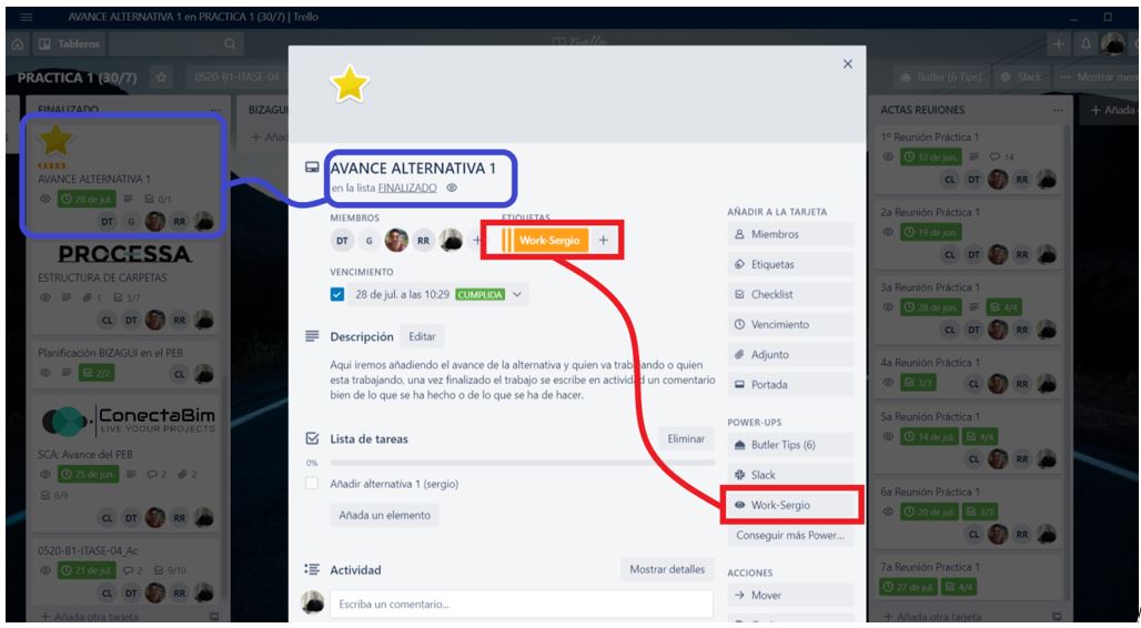
TRELLO platform example
On the SLACK platform , we created team and project discussion channels, where we discussed progress, questions, and changes as they occurred to keep everyone up-to-date on their progress.
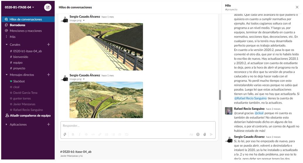
Example SLACK platform
To reflect on the project’s progress and milestone achievements, a weekly virtual meeting was scheduled from the outset. Each team member discussed their progress and needs. Minutes were then kept of all agreed-upon commitments, and the entire team was consulted on commitments.
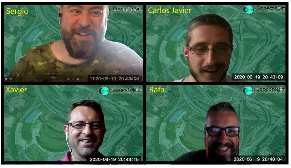
Example of virtual meetings
Creation of the digital model
Preparation of the BIM Execution Plan (BEP)
The BIM Execution Plan (BEP) is a document that describes the procedures, resources, tools, objectives, and client requirements, which we refer to as EIRs (Employer’s Information Requirements). To create the BIM Execution Plan, hereinafter BEP, we adapt to the client’s requirements and the agreed points and sections. To develop these plans, we do not use a BEP as an example; we opted to seek information on the requirements of administrations when developing the document. To do this, we consulted the Ministry of Public Works’ “Guide for the Preparation of the BIM Execution Plan,” the Generalitat’s “BIM Guide,” and the “Generalitat’s BIM Manual.”
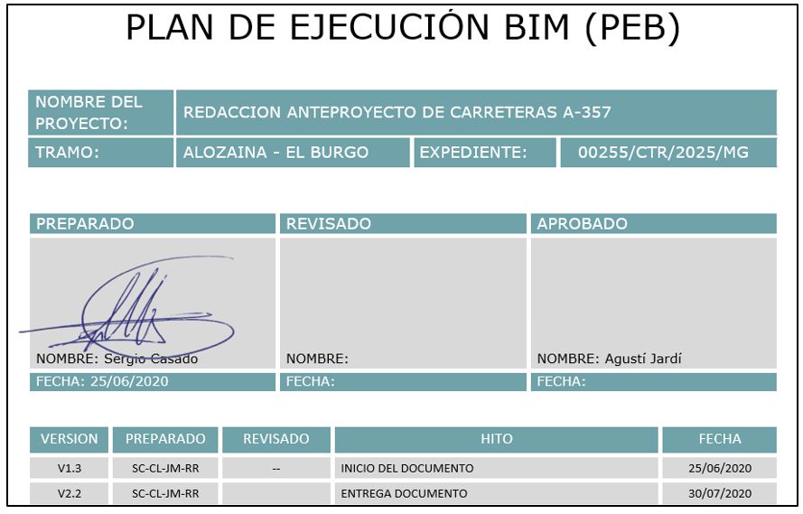
Cover of the BIM Execution Plan
Within the PEB we generate team roles to coordinate and plan flows and responsibilities.
Development team roles
- BIM Contract Coordinator : Coordinates the work teams and is responsible for compliance with the project’s BIM requirements.
- Design Coordinator : Responsible for the requirements and quality of the design, ensuring the levels of detail and development of the modeled elements.
Roles of the production team
- Discipline Manager (TRA) Layout: Responsible for the design of the linear work layout, procedures and organization in the modeling of the elements in the different phases.
- Discipline Manager (EST) Structures: Responsible for the design, calculation and modeling procedure of the elements.
- Discipline Manager (INS) Facilities and Services: Responsible for grouping information and responding to potential issues, integrating the information into the models.
- Discipline Manager (URB) Urbanization and environment: Responsible for the environment and the digital terrain model on which the different disciplines are modeled.
- Discipline Manager (GIS) Geographic Information Systems and Cartography: Responsible for managing alphanumeric and digital cartography databases using QGIS for the implementation of geographic information systems in associated projects. Incorporating environmental data into the GIS, maintaining and continuously updating the information, as well as producing periodic reports on the managed indicators and the impact of the implemented measures in the region.
- Discipline modeler: Agent assigned to generate the model with the conditions and requirements of the person responsible for the discipline.
Preparation of the process and coordination diagram
BIZAGI was the tool used for the workflow study, providing a fundamental basis for task planning and interfacing with the various software programs. Each agent has a schedule that identifies when they need to participate and with whom they share work information.
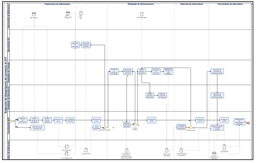
Appearance of the ConectaBIM team flowchart
A correct process diagram will ensure that the project is in balance and makes it easier to generate copies of the different states and control dedication times, as well as workloads and reorganize to make the tasks manageable. Just like the PEB, this workflow diagram must be updated when the project so requires.
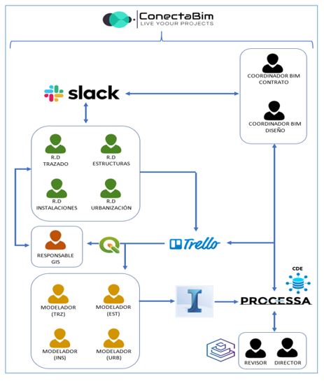
Traceability of information
Geographic Information Management (GIS)
Geodetic reference system and time zone
The reference system used is the one in force throughout the country following Royal Decree 1071/2007 of July 27, which regulates the geodetic reference system. The system adopted is ETRS89, and the time zone that reflects the scope of the project is 30.
GIS data management
Geographic Information Systems (GIS) are a tool that allows us to work with databases and perform multi-criteria analysis for decision-making. They have applications in various fields of engineering and civil engineering: cultural heritage management, urban planning, power grids, telephone wiring, topography, route management, sanitation and supply networks, study of route alternatives, etc.
The territorial and urban planning process involves handling large volumes of graphic and descriptive information. Geographic Information Systems are the technology that allows us to manage and analyze this information. The applications of Geographic Information Systems in civil engineering include the planning and design of civil works, management of public service networks, environmental protection plans, territorial and urban planning, and risk analysis.
Geographic Information Systems are the key tool for the management of any resource, whether natural or anthropogenic .
They allow for the development of basic cartography for resource management, which can then be analyzed, represented, and management strategies developed in a coherent, optimized, and viable manner. They include the generation of basic cartography, predictive models of species distribution, biodiversity management, environmental impact assessments, hydrological management, fire and forest management, natural space management, and pest and invasive species management.
Furthermore, by generating solid databases, analyses of changes in the territory and landscape are conducted. Therefore, both working methods become necessary and mandatory tools for any environmental professional in decision-making regarding territorial and landscape planning.
GIS, thanks to their spatial management capabilities, are ideally suited to assist transportation systems, allowing for the monitoring of parameters in various variables: Infrastructure Maintenance and Upkeep, Traffic Management, Impacts of new infrastructure, and Vehicle Navigation Systems. All this being said, for data management purposes, the information has been enclosed in a space containing the start and end coordinates of the section under study, which you provided in the study order.
Within the project scope, we have configured the QGIS tool to integrate the different layers of interest for the project into this scope. The person responsible for the discipline has generated a document with the information downloaded from the official pages of the IDEE geoportal, the CNIG download center, the State Nature Data Bank, and the DERA of the Andalusian Regional Government.
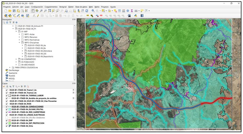
Composition of information in the QGIS tool
With the information collected by the GIS agent, all layers were exported in SHP for use in the Autodesk Infraworks modeling tool.
Creation of the digital model
Importing cartography and GIS data
To generate the maps, dense clouds were managed using the Istram/Ispol tool . They were removed along with the elements that did not affect the terrain, and the contour lines were generated. This resulted in two exports: a shape with the contour lines and a LandXML file.
Subsequently, in the Autodesk Infraworks tool, we imported the terrain information and GIS layers with the information from the database to select the alternative corridors.
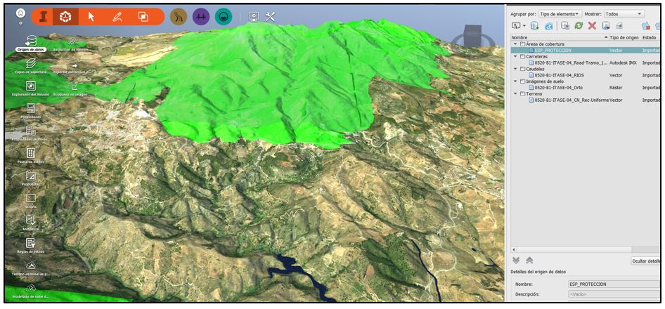
LandXML of terrain, orthophoto, and QGIS imported layers in Autodesk Infrastructure
Modeling and design of alternatives
As Mr. Agustí Jardí (director of the Master’s Degree) would say, ” once the groundwork is laid, we get down to business ,” and so we did, continuing with the BIZAGI workflow plan.Two models are created, each describing an alternative, and are delivered with Infraworks modeling information to reduce file size. Two agents are dedicated in parallel to designing the corridor for each alternative.
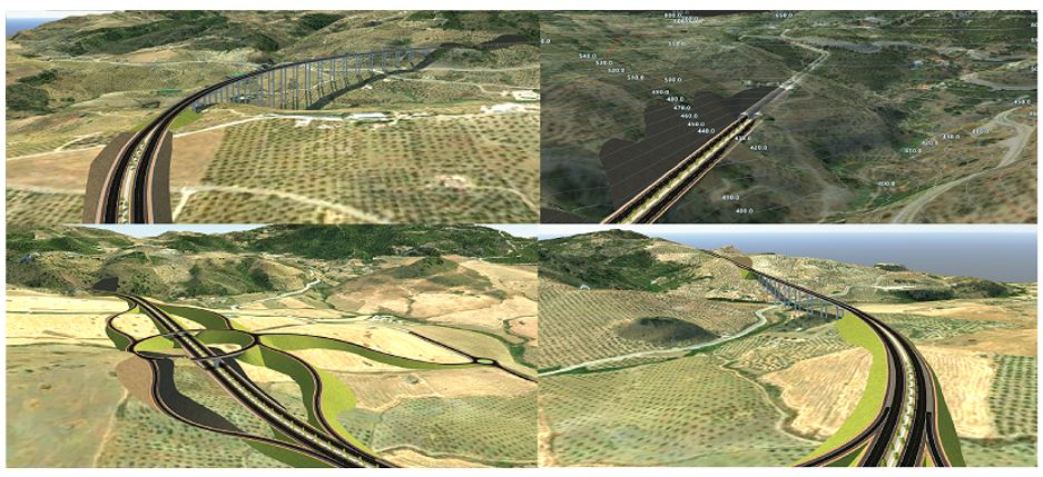
Alternative 1 runs along the southern area of the municipality of Alozaina, about 500 m from it, southwesterly between elevations 250 and 350 m, reaching the Arroyo de los Valles via a 671 m viaduct (at a finishing elevation of 708 m), which is crossed by another 398 m viaduct (at a finishing elevation of + 305 m), heading west towards the Sierra de las Nieves on its northern slope, crossing a first double-entry tunnel of 442.50 m and continuing to a second viaduct of 912.60 m (finishing at an elevation of + 350 m) until reaching the foot of the mountain range, which is crossed by a second tunnel of 4.862 km, until reaching the plain of El Burgo, where the connection with the A-366 is made, with 2 roundabouts at the height of the municipality of El Burgo.
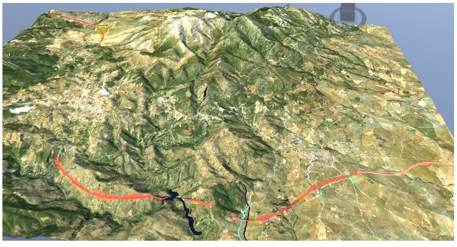
Alternative corridor 1
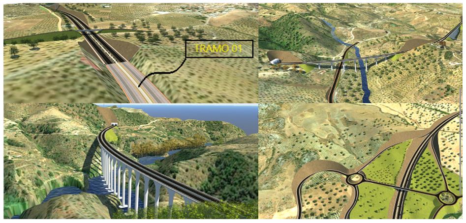
Alternative corridor 1
Alternative 2 starts from the same point in the direction of the Arroyo de los Valles, crossing this depression via a 602 m viaduct (at an elevation of 400 m) and heading further north, between the gorge and the southern slope, in search of the Yunquera road, to head towards the Sierra de las Nieves. Approximately 1,300 m from the viaduct, a 5.795 km double-entry tunnel is built until reaching the El Burgo plain, where the junction is made with an elevated roundabout over the main trunk where it embraces the A-366 at the height of the municipality of El Burgo. After this, until reaching the end of the section, a second 681 m viaduct is built (at an elevation of +650 m).
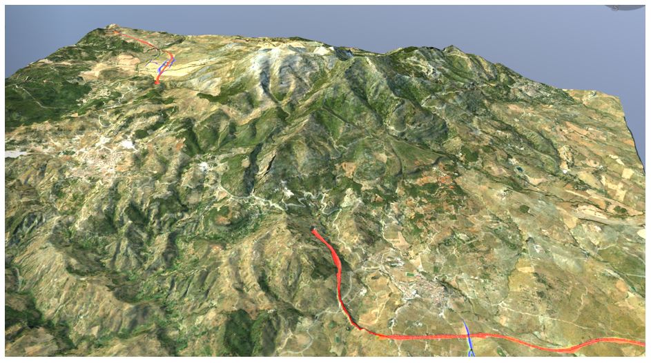
Alternative corridor 2
 Alternative corridor 2
Digital models are composites containing a large amount of information, so the workflow is based on classifying the elements that appear in the model. Thus, we created typical sections that could be generated with and without decorative elements. Preparing the bases allows us to be agile in making modifications in subsequent projects. Our philosophy is to always consider the modifications that any of the elements we create could undergo. This ensures a growing workflow, in which modeling times are optimized as the project progresses. When creating the sections, we separate each element and relate it to the element classification table. For subsequent studies, the classification table we use is the GuBIMclass.
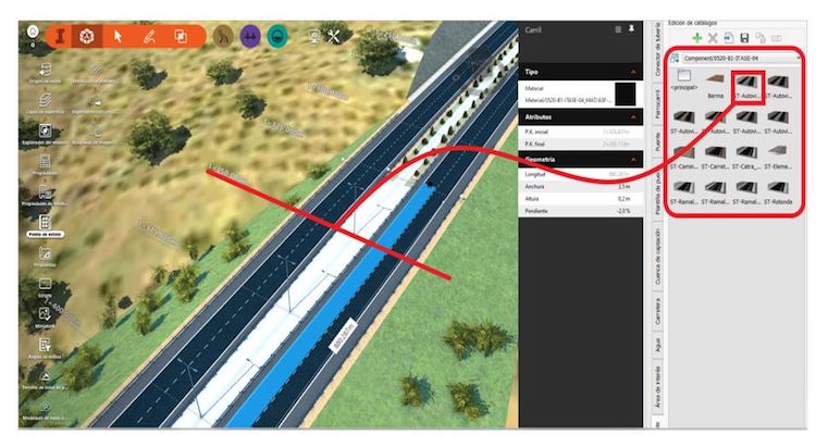
Catalog of composite sections applied in the model
In parallel with creating the sections to be used in the design of the alternatives, the design agent compiles the decorative elements involved, such as parapets, guardrails, concrete barriers, trees, and lighting, among others.
Among the creative elements, we created a two-eye tunnel to provide a solution for a highway platform, since this type of platform, due to its size, cannot be built with a single bridge. To create the bridge, we used Autodesk Inventions, where we created the typical tunnel section. We created the tunnel’s flute peak with 3D Studio.
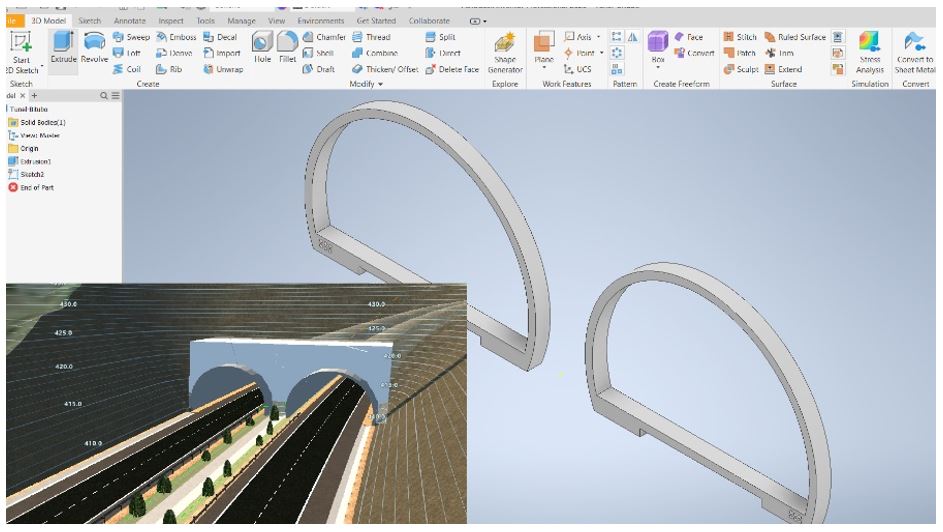
Catalog of composite sections applied in the model
To create the links, we omitted the option offered by Autodesk Infraworks on the automation of branches and manually generated the acceleration or deceleration lanes with the decomposition and insertion of components, giving entry or exit transitions to generate the wedges, with the distances of wedges and lanes based on the Technical Instruction for road layout 3.1 of December 2016. To assemble the axes of the branches, we used the information on elevation, slope and superelevation that appears in the longitudinal and transverse profiles of the axes.
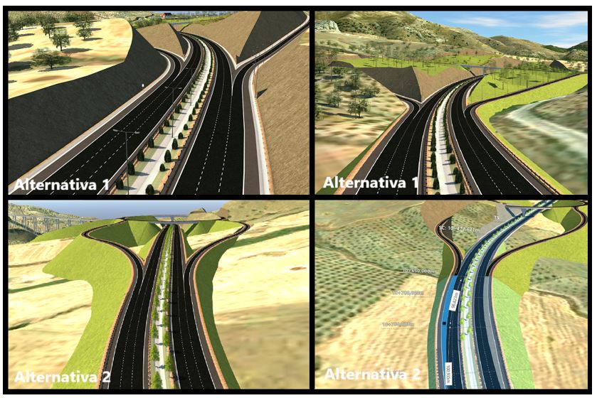
Links to the two alternatives
Once the layout was resolved, the decoration of the two alternatives continued, giving more detail to the selected alternative.
Document management
To implement the contract within a collaborative framework, an environment for document management and transfer is defined, applying a structure based on PAS 1192-2. These will be hosted on ConectaBIM servers and in the CDE PROCESSA manager, which is managed by Zigurat’s responsible agents.
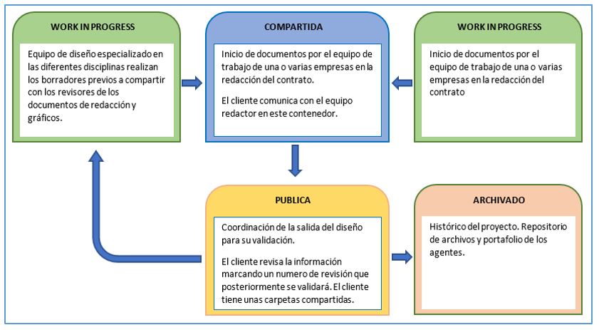
Workflow diagram
The structure is made up of a WORK IN PROGRESS folder that is hosted on the ConectaBIM servers and is only accessible by the drafting team. On the PROCESSA platform, only the existence of the container with information on how the data is organized is shown for informational purposes to show the internal organization, but the work information is not hosted in order not to saturate the PROCESSA space. In this container, work will be carried out by team disciplines. The SHARED containers and the PUBLIC CONTAINER can be accessed by both the drafting team and the ZIGURAT team and are located in PROCESSA. In the SHARED container, the progress and advances of the project are uploaded in order to see the status and progress where the number of versions will be validated and controlled. From here, the information can be returned to WORK IN PROGRESS for correction or the latest version will be copied to the PUBLIC container, where the deliverables are published on the scheduled dates. The ARCHIVED container is hosted in PROCESSA and stored by ZIGURAT, where the history of project deliveries that have been validated will be kept.
Conclusions
In conclusion, when generating models, it is important to have a well-written BIM Execution Plan where stakeholders can consult the objectives and a workflow process that optimizes the project. The information managed in these projects can slow down the work, therefore, the execution order is important: first create the bases, design the corridor, generate the standard sections to be applied, prepare the secondary roads, paths, or branches, and once resolved, finish with the decoration. For subsequent modifications, it is necessary to have saved versions of the different states, to recover to a state without the secondary decoration information, in order to make modifications quickly. A poorly coordinated team can result in inoperative models that cannot process the added information, thus leading to a collapse.
To optimize teams, roles must be selected considering the strengths of each team member. Gamification of these is necessary, such as detecting through questions, intentions, character, commitment, the ability to concentrate in moments of tension, staying focused, and being efficient. If all this is taken into account, teams are balanced and therefore efficient.
Today, government portals already have a wealth of information where we can initiate digital models from the very beginning of the project. BIM/GIS collaboration is setting a course that enhances workflows. And looking at the trajectory, we can see that the information we access through Clivi is increasingly of higher quality.


