


V&A Dundee Museum: Shaping the sea
Project
Published by:
Datasheet
Description
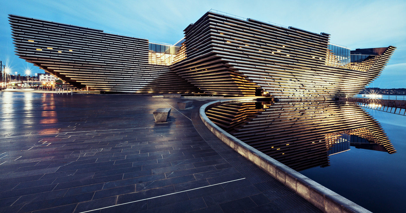
Located on the shore of the Tay River, the brand new V & A will become one of the most astounding buildings to open in 2018. The design by Kengo Kuma was inspired by the Scottish cliffs and it's also a nod to the form of the RRS Discover, the last traditional wooden ship built in Britain, now turned into a tourist attraction.
The building stands 18.4m high and has three floors. With no straight lines in the external walls, nearly 2K precast panels in order to look like a cliff. The shape of the building, who leans inwards and outwards, has been made with a hybrid structural skeleton, using reinforced concrete for the core, and internal and external walls, with structural steel for both first and second floors and the roof level. To get in, visitors have to cross a footbridge surrounded by water which runs through a tunnel.
BAM began to work in the project in March 2015. “The core is the backbone which gives stability,” explains Malcolm Boyd, construction manager at BAM. “Shears extend outward from the core, supporting the leaning external walls. The outside walls also depend on the floors and roof for stability, so the whole structure is interdependent.”
The challenge of building a museum inspired by the sea
During the building process, up to 11K square meters of formwork and nearly 1K tones of falsework were used to make the external walls. The design of the works was designed by a Peri team and later manufactured in different locations both in Germany and the UK. “We tested a complex section of wall, with a sloping and sweeping curve,” says Boyd. “Reinforcement is normally set out with 150mm centers, but because of the slope and angle, these centers had to reduce where the wall starts to curve.”
With up to 800 to 1K square meters per month manufactured, every shutter was bespoke for the project. Nearly a team of 30 workers was needed for the on-site construction, split into teams of five. “The outward-leaning shutter would go on first,” explains Boyd. “We used EDMs to scan the shutter, take readings, and draw up a heat map on the screen. Green indicated areas where the shutter was within the required tolerance. Where there was amber and red, it was outside the required tolerance which meant adjusting the four corners of the shutter. “The EDMs were linked to our BIM model for the project, so we knew precisely what the tolerances had to be. It was quite unusual to use this process for formwork but normally we build vertical walls!”
“The BIM model included the coordinates for where these Halfen channels needed to be located,” explains Boyd. “The positions needed to be accurate to within 2mm either way for the Halfen channels. Once this was achieved, the steel reinforcement fixers came in and then finally we could fit the internal shutters.”
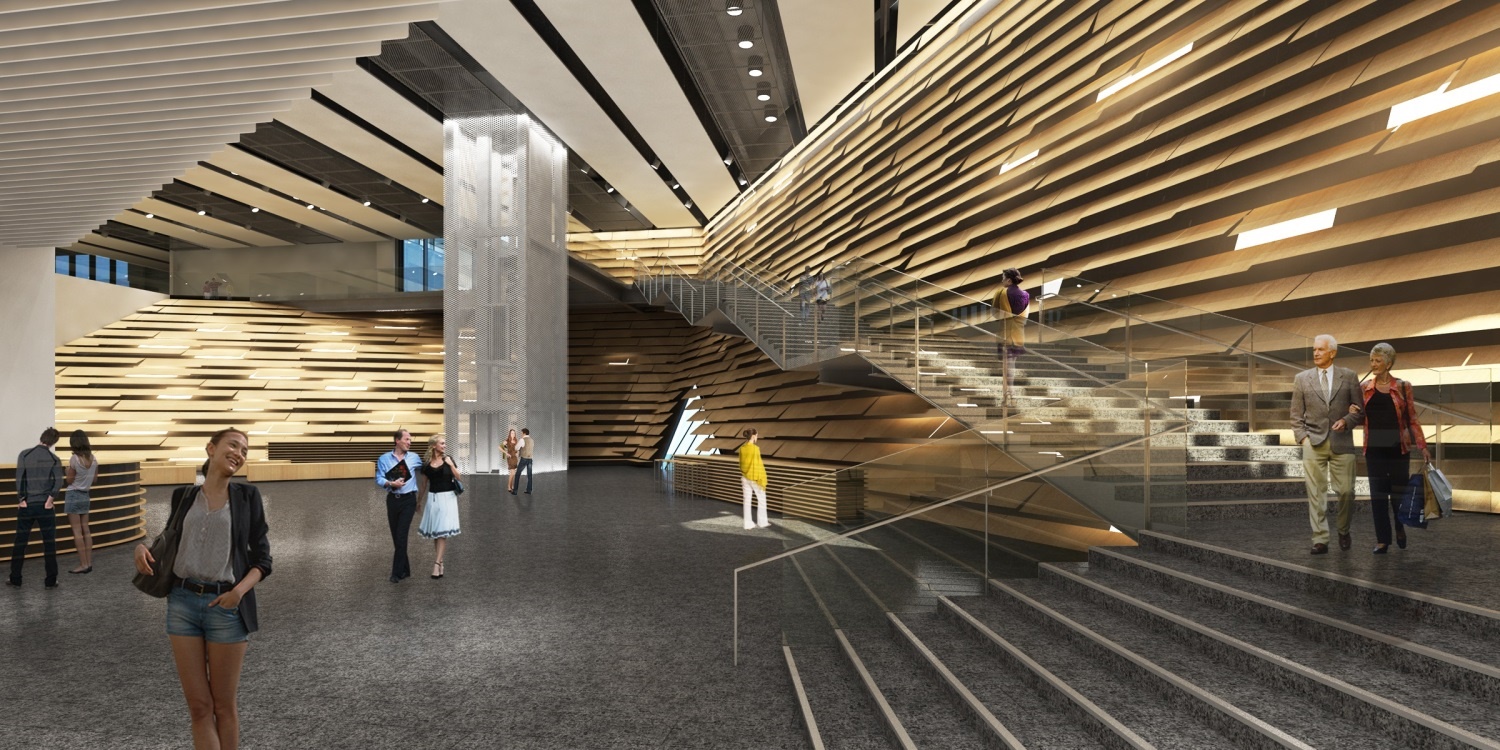
Image source: The Architect's Journal
Modeling with BIM
A 300mm thick slab on steel driven piles was used around the building perimeter to support the temporary works. “After a discussion with the architect, we decided to retain the base for the ponds which encapsulate the building – the design concept is for the museum to appear as if floating in the river,” states Boyd. “The rest of the pond bed we tanked later.” Due to the building design, the temporary works had to support the building during the construction process.
“Some of the shutters were 2m to 3m deep due to curves, so we had to strengthen the timber to transfer the loads from the permanent structure,” explains Boyd. “At various points where the shutters couldn’t support the loads, we installed mega shores, 17 in total, around the building.
“Our concrete subcontractor Carey employed engineering consultant Alan White to check how the loading paths in the structure were affected as the concrete pour progressed,” says Boyd. “After each lift, they would analyze the loading and provide a new set of propping drawings, and we would add the extra props as required.”
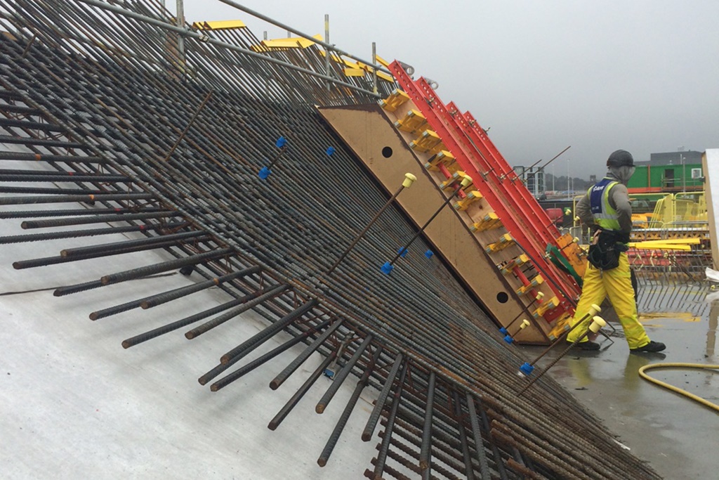
Image source: Construction News
The external walls, the last piece to finish the V&A Dundee Museum
Once the building was constructed, it was the time to start working in the external walls. The process began in September 2015, when the first shutter was placed. It took more than 2K cu m of concrete and 1K tonnes of reinforcement.
The concrete used in the project included a black pigment and Zemdrain, a form liner used in marine projects because of its water-proof property. “It also gives good consistency in the finish and provides a dimpled effect similar to a patio slab,” says Boyd. “Zemdrain comes in rolls, a bit like wallpaper, with an adhesive layer that is stuck onto the shutter. When the concrete gets poured, the Zemdrain draws off the water.”
Three weeks ahead of schedule, structural works were completed with the removal of the final shutter. Techrete was in charge of the design, manufacture and installation of the 2K precast panels for the V&A Dundee's facade. The process began in June 2015. “Every single precast plank was modeled by Techrete, which allowed us to go into the model, zoom in and spin the plank around to check it fitted the design,” says Boyd.
“Once we removed the shutters, the brackets for each plank were then located using coordinates taken out of the model, and EDMs were used to measure their position on site. Hooks were cast into the back of each precast plank, so in theory, once the bracket was located, as long as the precast plank modeling was correct, they should fit into position first time. As it turned out, we had an issue with only one out of the 2,429 precast planks.”
Archie Fotheringham, northern region contracts manager for Techrete, adds: “The fixings were specially designed with marine grade materials to ensure there would be no corrosion, given the museum’s marine location.”
“The programme was initially intended to install all planks in a 36-week period, but because of the BIM modeling and use of the EDMs, along with the preparatory site works, we were able to reduce this to 28 weeks,” explains Fotheringham. “On occasions, we were installing up to 22 planks per day.”
“The higher level planks were fitted using mobile cranes, but the lower level sections, which are underslung, were installed with bespoke lifting equipment, which we designed with one of our specialist suppliers,” says Fotheringham.
Type of Work
- Building
Companies collaborating in the project
- BAM