


Point Cloud to BIM Process with a Real Life Project
Project
Published by:
Datasheet
Description
When we talk about Scan to BIM, we talk about a process and series of steps that we implement to get an actual representation of the existing conditions of a project. We may question its applicability and about who all can use this process.
So keeping it brief, when we have an existing building in place and we want to bring some alterations like retrofitting, renovation, refurbishment, or reconstruction; where we aim to keep established structure and system in place. In that scenario, it is very important to have a detailed and accurate representation of the existing conditions of the building. A 3D laser scanning device is used to capture the existing conditions, the scanned data is in the form of “Points” when millions of such points are combined together that formulates as a Point Cloud Scan. A Point Cloud Scan is then imported into a 3D Modeling platform with the purpose of creating an As-built model.
The intended use of Scan to BIM process can be for: site verification, design validation/planning/comparison, develop as-built drawings, interference checks, MEP or construction elements demolition, or addition, documentation of existing building conditions, quantity take-off, and budget estimation. In the process of documentation, the following are levels of documentation
Level 1: Floor Plans
Level 2: Exterior Elevation & Roof Plans
Level 3: Sections
Level 4: Site Plan Layout
Execution of a Scan to BIM project can be very challenging, to implement the project successfully we have made a step-by-step process, which is described below and involves four steps [1] Capture [2] Process [3] BIM Modeling and, [4] Quality Assurance and all four steps should be executed as per BIM Execution Plan (BEP/BXP) and as per project workflow.
1.Capture
In this phase, we gather as much information we can gather from the field and from the client about the project. We define the Scope of Work (SOW) at this stage, Level of Detail (LOD), timeline, and a deadline for the project. It is very important to have a descriptive Scope of Work (SOW) because that will define the inclusion and exclusion of all the trades. For a Scan to BIM project, capturing of the information takes place in two phases.
(i) Pre-Mobilization Considerations
Pre-mobilization consideration is for taking into account all the information regarding Scanner selection and pre-planning of the site-work before arriving on the site. Also, it includes ensuring necessary requirements with the United States Institute of Building Documentation (USIBD) Level of Accuracy (LOA) aligning with the BIM Execution Plan (BEP/BXP). Different laser scanners have specific strengths and weaknesses, hence, it is important to do the cost and benefit analysis of all. Evaluation of the scanning device is important as it should align with the need for the job and capacity of the scanner.
(ii) On-Site Information
Confirmation of site conditions is very important. The scope area should be properly invigilated before commencing the project. A thorough study needs to be done by standardizing and creating template worksheets that can help assure the quality of the end-product (i.e., BIM Model). With the information regarding the existing conditions of the building, best-suited training should be given to the team to execute the project.
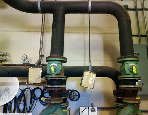
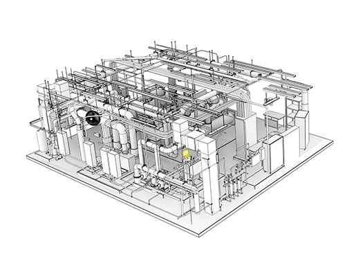
Capturing for the existing conditions of the building will take place by placing the scanner on the tripod and it will capture the building with high speed and precision. The device has an eye-safe laser rotating at high-speed. It is generally placed on the tripod at the site, and as and when the laser beam hits any solid surface, it records its position as coordinates known as “points”.
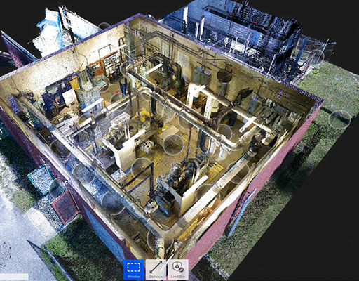
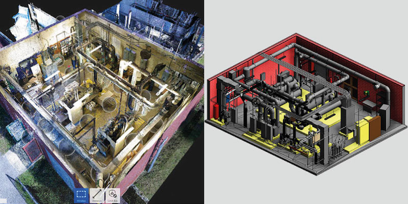
Point Cloud Scan Data of Mechanical Room
Point Cloud Scan of Mechanical Room- Zoomed In View
2. Process
After, capturing the as-built conditions of the building, the next step is to process the scan. This is a very important step which includes validating the survey data regardless of its accuracy. Inspection of the scan should be performed to check the interruptions in the fluidity of the data, which may be caused by an environmental vibration and may not be caught by internal system checks. In order to process the scan data, it is important to break the datasets into clusters and to always keep a copy of data prior to any manipulation.
Next comes post-registration of the scan data. Here, the alignment of the data plays a major role. The different applications can require different techniques to align like- best fit, ortho, geo-referencing, etc. One should always manually check the scan data to avoid any kind of overlapping or any error. A Point Cloud Scan may seem to be dirty or noisy which may be difficult to correct the elements. So the initial setup is important to register and load the point cloud scan completely.
Autodesk’s ReCap is a high-performance software capable of creating an intelligent 3D model, from captured photos and laser scans in a streamlined workflow. This software makes it easy to clean, organize, and visualize massive datasets from the Point Cloud Scan.
There are two types of Point Cloud File Types
-RCP: Autodesk ReCap Scans (Individual Scan File)
-RCS: Autodesk ReCap Projects (Project File that references indexed scan files)
Mechanical Room Outer View
Mechanical System View
3. BIM Modeling
Modeling is where the Point Cloud, a real-life scan of the project gets shape in a digital platform. To model the Point Cloud Scan, several steps need to be followed from Verification of the Point Cloud Scan, Project Information to File Insertion in Revit, and File Set Up. These steps are briefly described below:
(i) Verification
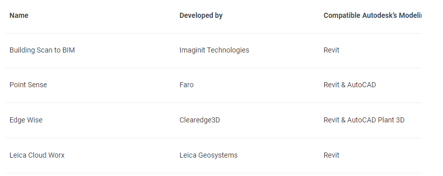
Before commencing modeling, it is important to have a clearly communicated Scope of Work (SOW) which will define trades to be included or excluded, Level of Detail required by the client, and other necessary details. It is also suggested to have a clearly defined tolerance level of deviation for a successful implementation of Scan to BIM Execution Plan (BEP/BXP). To start with the modeling process, the coordinates of the point cloud needs to be verified. Some widely used software are:
(ii) Insertion
Then after all the verification, insertion of the point cloud scan takes place into Revit. In case if there are several Point Cloud Files it is important to assure the integrity and coordinates of all the files at once. Once the file is inserted into Revit. We must lock it down with the Pin Tool to pin it to a specific location as it earns speed when the mouse passes over the Point Cloud Scan.
(iii) File Set-Up
To start the process of File Set-Up in Revit, worksets needs to be created according to the need of the project. It is recommended to use different worksets for each Point Cloud in order to set the VVGG setting and turn on/off as required. This also reduces the opening time of the file. One should use a different workset for elements imported from the conversion tool used. To set up the levels from a Section View, ensure to lock it. The following can be the levels:
Level 0: Level 0 should be set through the Origin Point of the Point Cloud Scan. It can/cannot be with the Project levels was it will be the reference point.
Building Levels: It will depend on the project. The modeler must set the level line through a representative part of the floor that the Point Cloud is showing. For setting up several levels in the model at a time, we can place the Section through a stair core.
Set Plan View: It will be set according to the created levels by the modeler.
Girds: Girds should be set up by using the main floor of the building and set an objective of the grid system throughout the model with regular distance wherever possible.
(iv) Modeling
When it comes to modeling there are few guidelines that should be followed in the BIM Execution Plan (BXP). All the elements must be modeled as a single correct Revit Elements, a group of a single column must be used, instead of a generic model with # of extrusions. All the elements must be hosted to the corresponding levels. The walls of the model must be best fitting to the Point Cloud by cutting thin view angels in plan and section views. When modeling a perimeter wall in a plan view, always select the option of Interior/Exterior Finish as wall constrain, in order to follow your known wall face location. The purpose behind this is that the real data of wall thickness can be updated later and the established perimeter will still remain in the correct place.
(v) Collaboration
Communication is vital when it comes to modeling, every necessary information must be clearly communicated and defined with all the participants. All the participants involved must have access to the same storage disc of the Point Cloud where it is saved. If not, all the participants will save the file into their own system and would like the file from there. It is important to use compatible software, version, and updates. When it comes to collaborating with the project, it would be better to have a control model for the setup of levels, grids, and shared coordinates, if needed. By this, none of the participates will be able to modify, move, or delete the information. There is another important key to the modelers since they have to work on heavy files, it is important for them to have a backup.
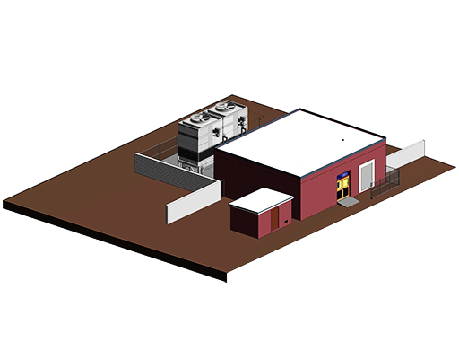
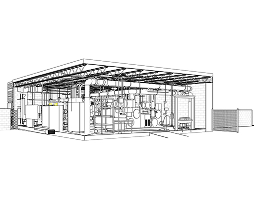
Section View of Mechanical Project

BIM Model of Mechanical Room
4. Quality Assurance
There are few QC process steps to be followed after modeling in order to ensure the quality of the model. Firstly, run a quick round of model check by throwing a section and move it across the project. By using the visibility and override options to check on specified elements. It is advised to do a thorough comparison of a delimitated area by using Plan, Section, or 3D view. To check the clashes between Mechanical, Electrical, and Plumbing disciplines, use Autodesk’s Navisworks as it provides a lighter and easier way to navigate a Revit Model. It is very important to clean the file to delete all the reference points and detailed lines from the model.
Conclusion
To get the crux of Scan to BIM process, Scan to BIM is basically a practice of creating a digital representation of existing conditions of the building with its physical and functional characteristics in BIM. A laser scanner is devised to capture an accurate 3D scan which is then imported into 3D BIM software in order to create either accurate as-built models or to capture the design with the real-world conditions. This process is carried out in 4 major steps: Capture, Process, BIM Modeling & Quality Assurance. It starts with capturing the building with a laser scanner, processing the Point Cloud Scan so that it is clean and verified for the use, Modeling the Point Cloud Scan by inserting the data into the modeling platform, verifying it, and developing a BIM Model. It ends with verifying if there is any deviation and of the disciplines are coordinated (i.e. Clash Detection).
Type of Work
- Building