


BIM on Karavanke Tunnel
Project
Published by:
Datasheet
Description
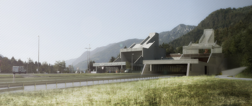
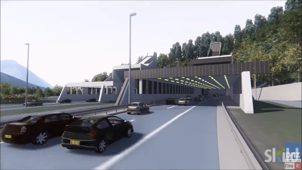
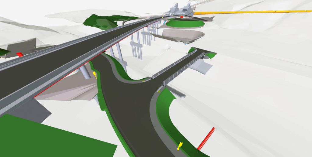
Asfinag and DARS (Motorway Companies in the Republic of Austria and Slovenia) hired Elea iC to support the design of the second tube for the Karavanke tunnel project, an 8.0 km long, single tube, bidirectional motorway tunnel connecting Austria and Slovenia.
It was originally designed as a twin tube tunnel, but due to lack of traffic, it was built as a single tube. After commissioning, increasingly higher traffic, support deterioration and lack of safety measures meant that a second tube was required to efficiently operate the tunnel in the future.
Goal of the project: Pilot BIM
The goal was systematic implementation of BIM methodology to the project and exploring the benefits and challenges through planning, executing and controlling BIM related activities including the following:
- Creation of comprehensive Employers Information Requirements that the client will also use in future projects
- Creation of comprehensive BIM execution plan that the client will also use in future projects
- 3D modeling (Design and As-built models) 4D and 5D modeling, Model-based quality control
- Geological and Geotechnical modeling
- Use of models in operational phase
- Further development of existing CAFM – Computer Aided Facility Management system.
Unique challenges
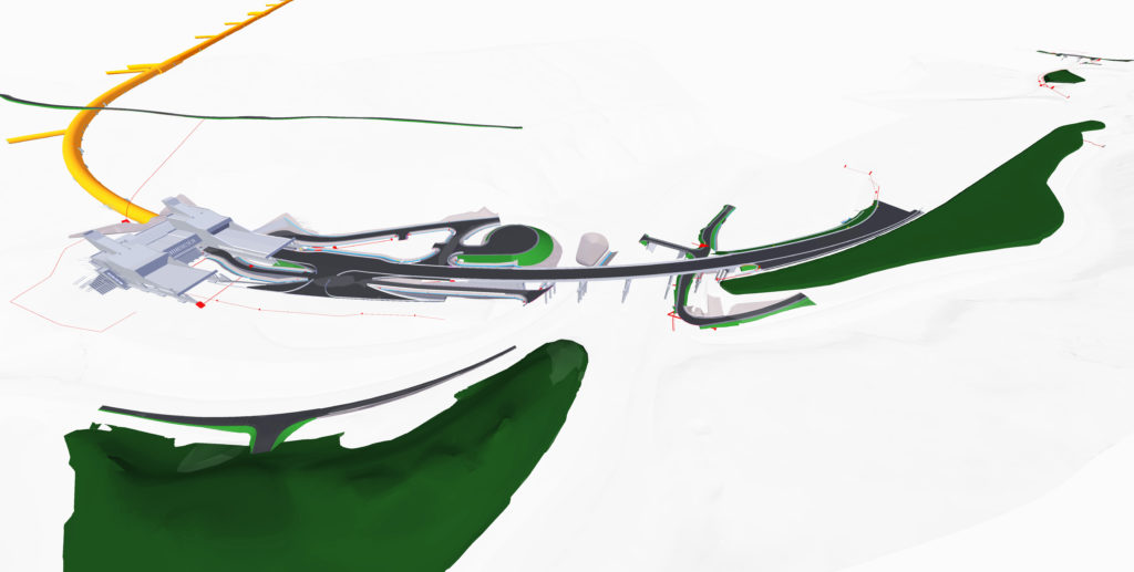
What makes this project unique is the complexity of the project scope including tunnel, highway and several minor roads, 3 bridges, retaining structures, portal buildings, utilities, disposal areas, etc. Also, there is the complexity of project organization (2 client organizations, 1 supervision company, 10 design companies currently involved in BIM design process) and the variety of BIM software (5 different design authoring tools) used on the project which encourages the team to push the limits of an open BIM approach.
App. 190 partial models are being exchanged across disciplines and coordinated in 5 Coordination models using IFC and BCF standard for interdisciplinary collaboration.
A closed BIM approach is used in each discipline to maintain the maximum efficiency of design process. In order to improve the interoperability and ensure quality of BIM deliverables a tunneling data structure is being developed on the basis of existing IFC standards so it can be used for advanced BIM uses (e.g. 4D, 5D modeling, CAFM, etc.)
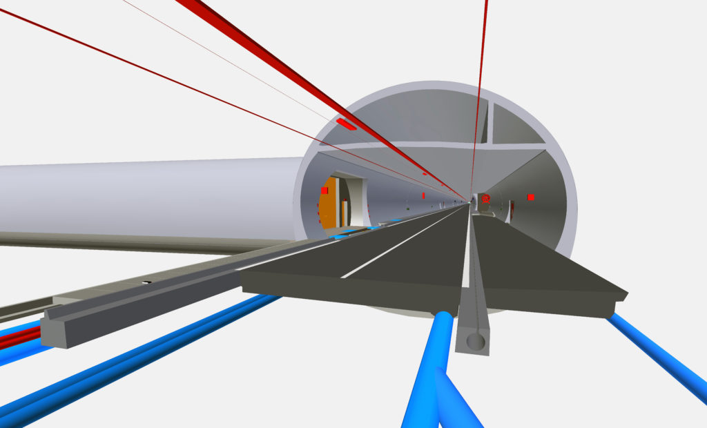
Revit in connection with Dynamo Scripting and special add-ons is being used for specific needs in case of modeling long and complex structure – the tunnel. This enables efficiency in modeling of long, longitudinal segments and detailing.
The exchange of 4D and 5D models between different software solutions (design team, supervision and future contractor) presents another challenge that is and will be managed with custom interoperability solutions.
Planning & preliminary engineering
The team improved the overall project development process with better understanding of special clients`needs (e.g. use of project information in operational phase, transparency of investment – improved project controlling, etc.). The analysis of requirements led to better planning of overall project development–documented in the comprehensive BIM Execution plan. BIM in early design stages provided the ability to visualize and communicate the design with all project stakeholders.
It was the first time that the all planned facilities, geology and infrastructure (scattered across 3 different project coordinate systems – Austrian, Slovenian national coordinate system and local coordinate system) was federated in one single model. The initial quantification and cost estimate (4D and 5D models) were created at that stage, which resulted in better understanding of project.
Detailed design
The team improved consistency of project documentation through performing constant quality control checks (identification of inconsistencies between partial models, evaluation of design changes, communication and implementation of design changes). Structural models were also used for reinforcement detailing which enabled time savings as several designers could model reinforcement in the same models simultaneously.
- Design changes during collaboration process and design development were implemented to other discipline models (and consequentially to drawings that were generated from models) more efficiently using BCF standard for model based communication.
- 5D model generated out of app. 160 partial models was used to double-check the quantities provided by different design disciplines and to create more accurate cost estimates.
- Cost estimates were presented to the client in various reports, spreadsheets and simulation.
- Maintenance services were able to comment design solutions using accurate 3D models right from beginning optimizing design against equipment available.
Integrated analysis & simulation
Autodesk Navisworks Manage was used to federate all partial models which were created in 3 different coordinate systems and linked the elements with time schedule created in Microsoft Project resulting in comprehensive 4D model which was used to analyze and optimize time sequence of activities. The benefit was that the project team was able to visualize time schedule and communicate suggestions for improvement.
The same time schedule and partial models were used to create 5D model in RIB iTWO software and analyze the cost estimates. 3D geological model combined with Revit Tunnel models presented a basis for 3D numerical analysis for tunnel excavation and support. In house program code was developed allowing direct communication between geological model and numerical models.
Communication & collaboration
Internal collaboration – closed BIM: Revit Server is used internally by disciplines that are using Revit as design authoring tool. Integrated communication and model sharing speeds up the internal coordination and design development, as many modelers can work on the same models simultaneously. Interdisciplinary collaboration – open BIM: IFC and BCF standard is used to share model between disciplines. The reason for this is that there are currently 10 design companies involved in the design development and a variety of authoring tools are used (Revit, Civil 3D, Allplan, ArchiCAD, Urbano).
A Common Data Environment (ownCloud and BIM Collab) is used to exchange files between disciplines and to link – synchronize IFC reference models and BCFs with design authoring tools, coordination models, 4D and 5D models. All other documents (drawings, reports, etc.) are also exchanged and stored on the same platform.
By using LiDAR for scanning the existing parts of the tunnel we were able to analyze requirements for future excavations, reprofiling and backfilling. Raw data from LiDAR was used elsewhere to produce accurate surface models. Augmented reality was introduced in the tunnel for better understanding of the surrounding geology. By using Virtual reality models we were able to efficiently communicate with several key stakeholders. Design solutions are readily available anywhere with sufficient data transfer by using stable cloud based solution. The model will be constantly updated during excavation in construction stage in order to gather all site information in 1 model for possible needs in the future.
Deliverables
Apart from traditional project deliverables (Drawings, Technical reports, etc.) also the following BIM deliverables are part of the submittal packages:
Design phase
- BIM Execution plan (BEP).
- Partial (discipline) 3D models provided in IFC standard format
- Coordination models and quality control check reports
- 4D and 5D models provided in a form of various spreadsheets, reports and simulation
Construction phase
- As built models in IFC standard format with linked as built documentation needed for facility management (central repository of as built data)
- Coordination models and quality control check reports
- 5D models to be used for progress reporting and controlling by contractor and supervision
One of the main requirements that is implemented through BEP in the modeling process and deliverables is a consistent definition of Level of Detail (LoD) and Level of Information (LoI). Classification of tunneling elements and attribute tables were created in collaboration with the Client (Supervision and FM Department) and implemented in models on special – project specific IFC Property set. The attribute tables will be further developed during the project development and incorporated in the models.
Results
- Consistency and accuracy of design documentation (Models, Drawings, BOQs, Cost estimates, Time schedules, Progress reports, etc.)
- Improved communication between project stakeholders (Common Data Environment, Model-based revision, visualizations, Model-based communication)
- Improved cost estimation and control, optimization of construction technology (sequencing) Controlling of construction progress and field changes Optimization of facility management processes
Type of Work
- Civil work
Companies collaborating in the project
- Asfinag
- DARS