Technical Area | Articles

The place to solve all your BIM doubts

HARNESSING LOD'S FOR BIM MODELLING OF INFRASTRUCTURES

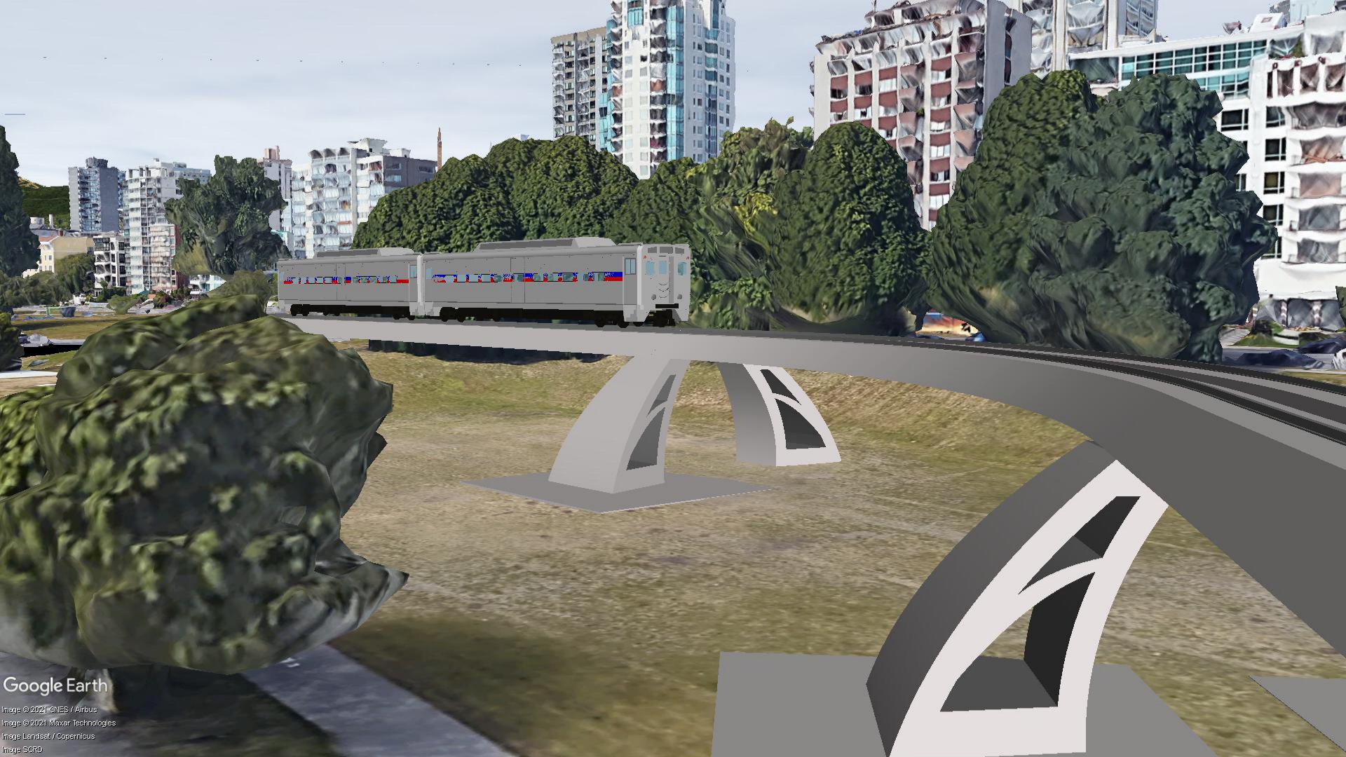
SKY-LINE TRAIN BRIDGE PROJECT

BIM Implementation 3D / VDC Infrastructures
profile_picture
Published: 09/03/2021

This is an infrastructural development whose sole function is to provide vehicular-train services in major cities of the world with case study in Vancouver, Canada.

Just as we do at Kalisode network, BIM (Building Information Modelling) and its associated cutting-edge solutions was the technological process adopted from start to the completion of the design phase of this project.

During conceptualization, the very popular BIM authoring tool; Autodesk Revit, was used to model the form and virtually all elements of the facility.

The project has been broken down into three phases; 

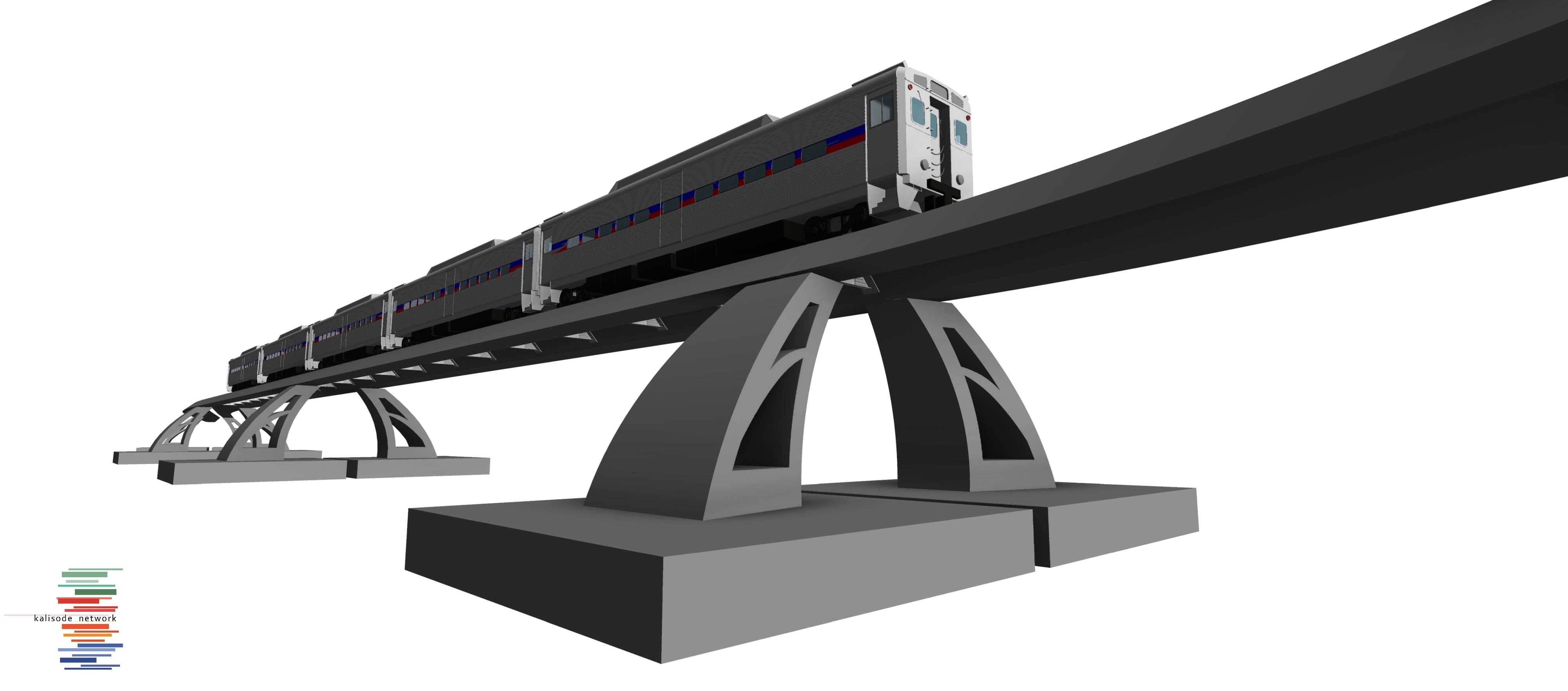
PHASE 1. Modelling of structural and functional components of the Train bridge


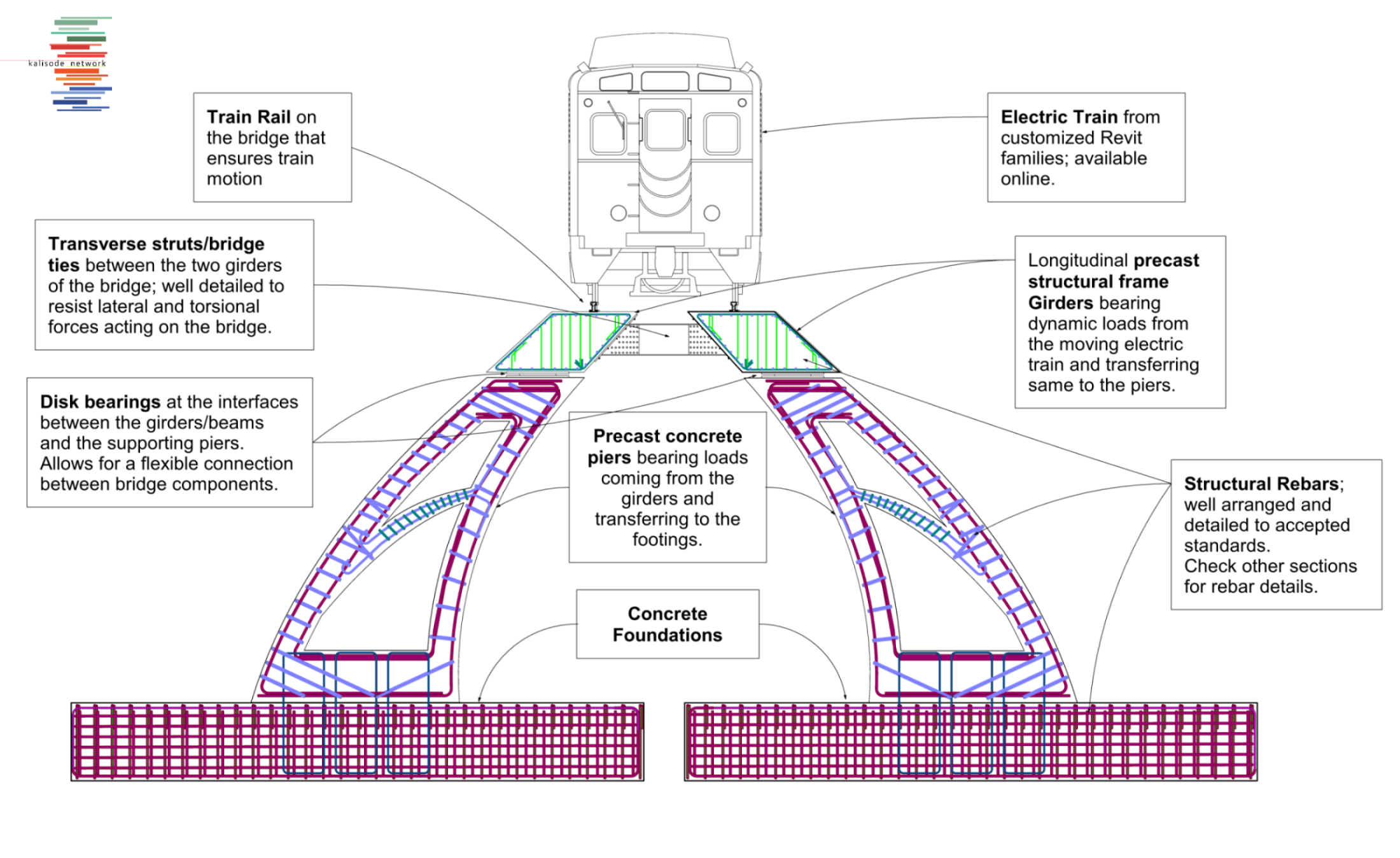
The functional components of the train bridge from top to bottom includes;


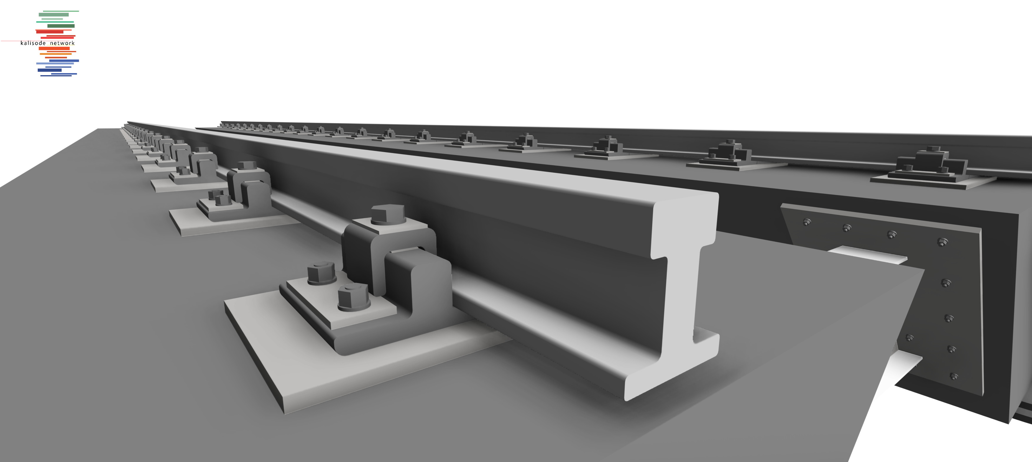
Train Rail: Serves as passage for the train vehicle, modelled with a hot-rolled steel material and has a I-shaped beam profile.

Bridge Girders: Modelled as bent beams/girders with an asymmetric center of mass, hosts the train rails and transfers dynamic reaction and torsional loads to lateral and underlying structural elements.

Disk Bearings: Modelled to provide a resting surface between the train bridge girders and bridge piers. It allows for controlled movements and therefore reduces the stresses transferred to the substructure.

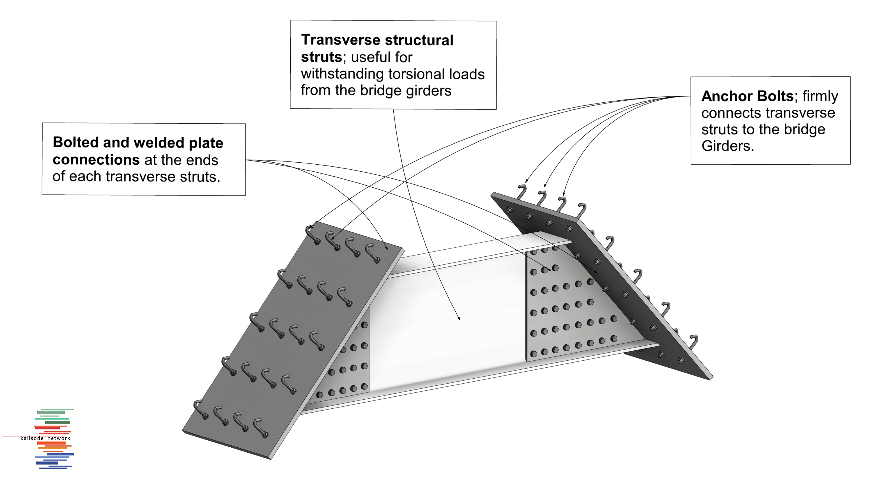
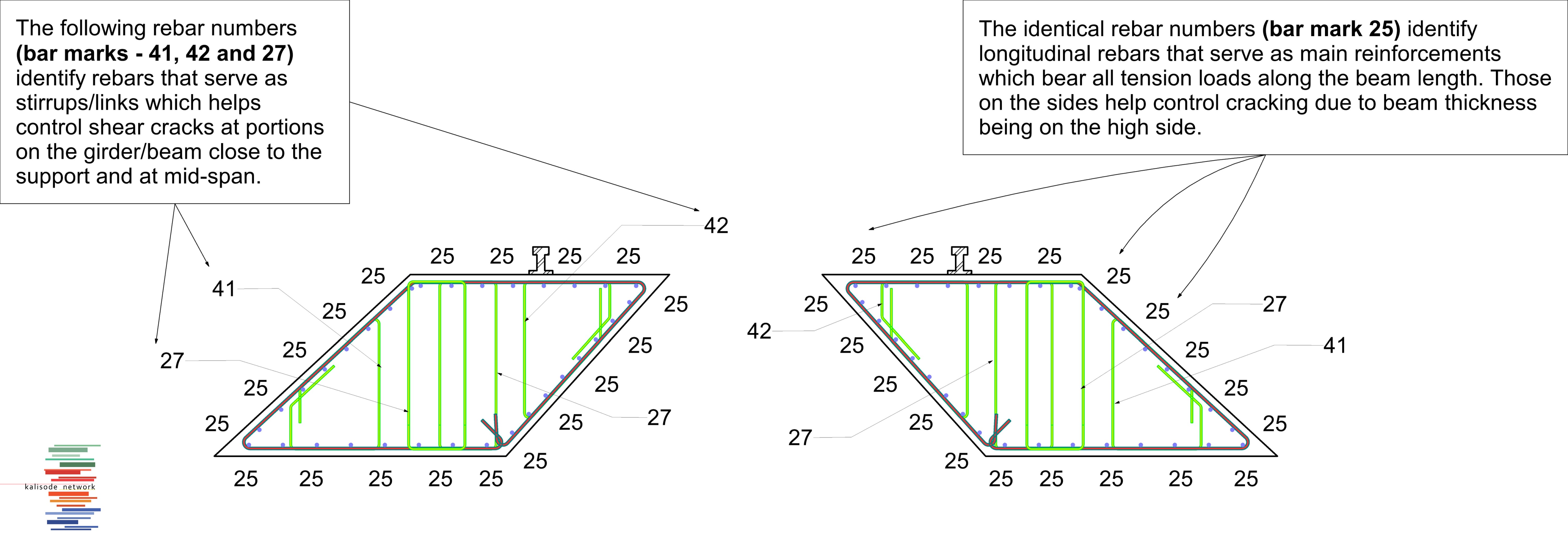
Lateral Struts: Modelled as a steel component which helps restrain lateral movements of the bent bridge girders and also takes up lateral, horizontal loads and torsional moments coming from moving train. The composite steel construction comprises of a combination of welded and bolted connections with end-moment plates.

Bridge Piers: Modelled as structural concrete columns with a smaller surface area at its top and a large surface area at its base with the intent to evenly distribute concentrated vertical reaction loads from girders to the foundation.

Foundations: Modelled as concrete spread footings with a large surface area to reduce stressing getting to the foundation soil. The spread footings are well reinforced to cater for extreme foundation stresses on whatsoever soil condition.


image

 image


PHASE 2; Rebar modelling and detailing

The functional components of the train bridge take shapes and forms that are not regular; hence having an asymmetric center of mass and high moment of inertia. For this reason, they require specialized and well detailed reinforcement meshes.

The maximum steel rebar diameter size utilized in this project is 32mm and is predominant in the pier and foundation elements.

Bridge girders takes up varying rebar diameters varying from 12mm and 16mm as transverse stirrups/links to 25mm as main longitudinal, tension-resisting reinforcements. Rebar detailing follows standard procedures provided by internationally accepted building codes.


 image


image


PHASE 3; Coordination with Realistic Environment and Global Coordinates

To integrate our model with a realistic environment having already developed real-life buildings in the chosen location (Vancouver, Canada); we decided to work with google earth pro maps because its features support our goals.

Since this project is a proposed development; modelling was carried out half way. However, a path showing the bridge route within the city was highlighted in Google earth pro; showing the extent of the bridge in its length.

image

Software
Revit Google Earth
Stay updated with the latest news, events, job offers, software and much more. Sign up to our monthly Newsletter and enjoy the best of BIM for free

Thank you for subscribing to the Newsletter!